5.6. Faint Object Spectrograph (FOS)
The FOS (7) was one of the original spectrographs on board HST. It obtained spectra between 1150 and 8500Å. It had two detectors with independent optical paths. One detector is more sensible towards the blue (FOS/BL, 1150-5400Å) and the other one towards the red (FOS/RD, 1620-8500Å).
The incident light goes through one of the apertures, a polarizer (in the case of spectro-polarimetric observations) and a filter (if necessary), it is then dispersed (by a dispersion grating or a prism) or reflected by a mirror (to create an image). An array of 512 diodes is at the end of the optical path. These diodes have a width of 0.31" in the dispersion direction (X) and 1.21" in the cross-dispersion direction (Y). The last one is measured in units called Y-base. The diodes have approximately 256 y-base units in height.
The different gratings and prisms produce spectra in different regions of the photocathode and on different groups of diodes. Figure 4 (from the instrument manual) illustrates the different apertures. In this example, the diode array is centered in the circular apertures.

|
Figure 4. The FOS apertures in the HST. |
FOS spectra were typically obtained using two techniques:
5.6.1 Apertures, gratings, prisms and polarizers
Tables 17 and 18 list the FOS gratings. Note that the name in the header is different from the one in the Handbook.
| Grating | Header Name | Wavelength (Å) | Width (Å/diode) |
| G130H | H13 | 1140 - 1606 | 1.00 |
| G190H | H19 | 1573 - 2330 | 1.47 |
| G270H | H27 | 2221 - 3301 | 2.09 |
| G400H | H40 | 3240 - 4822 | 3.07 |
| G570H | H57 | 4574 - 6872 | 4.45 |
| G160L | L15 | 1140 - 2508 | 6.87 |
| G650L | L65 | 3540 - 9022 | 25.11 |
| PRISM | PRI | 1500 - 6000 | - |
| Grating | Header Name | Wavelength (Å) | Width (Å/diode) |
| G190H | H19 | 1590 - 2312 | 1.45 |
| G270H | H27 | 2222 - 3277 | 2.05 |
| G400H | H40 | 3235 - 4781 | 3.00 |
| G570H | H57 | 4569 - 6818 | 4.37 |
| G780H | H78 | 6270 - 8500 | 5.72 |
| G160L | L15 | 1571 - 2424 | 6.64 |
| G650L | L65 | 3540 - 7075 | 25.44 |
| PRISM | PRI | 1850 - 8950 | - |
The values of the width for the red gratings are negative because the wavelength direction runs in the opposite direction. It is the same case for the spectra obtained with the prism.
5.6.2 What constitutes a "spectrum" obtained with the FOS?
An FOS "observation" is composed of several pairs of files whose name start with Y followed by eight alphanumeric characters. The header is a text archive whose extension finishes with the letter h. The binary data extension ends with d.
The following table briefly describes the different files (in GEIS format) that constitute an FOS "observation". More details about these files can be found in the HST Data Handbook.
Note that the calibrated "spectrum" is composed of two pairs of files that need to be combined:
| Extension | Contents |
| Uncalibrated Data | |
| d0h /d0d | uncalibrated scientific data |
| q0h /q0d | file describing the data quality |
| shh /shd | data packet describing the observation |
| ulh / uld | observation history |
| Calibrated Data | |
| c0h /c0d | wavelength-calibrated data |
| c1h/ c1d | flux-calibrated data |
| c2h/c2d | statistical errors |
| c4h/c4d | number of counts |
| c5h/c5d | "object" spectrum after flat-fielding |
| c6h/c6d | "sky" spectrum after flat-fielding |
| c7h/c7d | background spectrum |
| c8h/c8d | spectrum of the "object" after flat-fielding and sky subtractiont |
| cqh/cqd | quality of the calibrated data |
The calibration process produces several intermediate spectra (the output of the flat-fielding, sky subtracting, background spectra, for example) that can be used for further analysis.
Table 19 describes some parameters of interest included in an FOS header:
| RA_APER1, DECAPER1 | RA and dec of the aperture |
| PA_APER | position angle |
| OBSTIME | exposure time |
| APER_ID | aperture used (eg., SAA - small science aperture) |
| FGWA_ID | grating used (eg., G570H) |
| GRNDMODE | observing mode |
5.6.3 Number of pixels in the spectrum
The FOS observations obtained in ACCUM mode are made deviating the spectrum magnetically in the dispersion direction. The parameters SUBSTEP and OVERSCAN control this procedure. The most common case is the one with SUBSTEP=4 and OVERSCAN=5, each pixel in the spectrum (except the edges) is populated by contributions from 5 diodes. Despite the fact that there are 512 diodes, the number of pixels in a spectrum is:
For the values of the example above, the number of pixels is 2064.
5.6.4 Exposure time
Spectra obtained in the ACCUM
mode were read at regular intervals. Each group is the accumulation of
the counts of all the previous groups. The last group is the one that contains
all the counts accumulated during the total exposure time. It is then of
interest to know the different times involved in an ACCUM
observation. These times are listed in Table 20.
5.6.5 Analysis of FOS spectra
As detailed above, FOS calibrated
spectra are divided in two files: one wavelength- and the other
flux-calibrated.
To combine them and perform the analysis with the tasks in the onedspec
package, the STSDAS task mkmultispec
is used. This task modifies the header of the wavelength calibrated data
by including information about the flux. The data itself are not changed.
If the analysis requires,
for example, the combination of spectra obtained at several different
wavelengths, it is then necessary to use the resample
task. It is recommended, though, to avoid as much as possible tasks that
modify the data.
5.6.6 Orientation of the aperture
The acquisition mode of the spectrum (ACQUISITION or BINARY)
is indicated by the OPMODE keyword in the standard header packet (shh).
For OPMODE = ACQ the Right Ascension of the aperture
(in degrees) is given by the RA_APER1
and the declination (in degrees) by DEC_APER1.
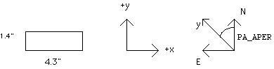
To obtain the position of the
aperture as it was in the sky, ie., with North "up" and East to the left,
the data can be rotated by the PA_APER
value. In the FOS coordinate system, the aperture is aligned with the X
axis parallel to the diodes (this is the side that measures 4.3") and the
Y axis is perpendicular to them (this is the side that measures 1.4") as
illustrated in Figure 5:
Figure 5. The size and orientation of the
FOS aperture in HST observations.
5.6.7 Flux determination for extended sources
All the calculations of the
flux described above were done supposing that the source was a point. It
is then necessary to correct these values for extended sources.
The steps to follow are:
(a) select the IVS file
corresponding to the 4.3" aperture and closest to the observation date
(use the DATE-OBS keyword to determine it)
(b) For the cases in which
the sources completely fills the aperture
the first factor is the
result of the division by the flat-field, the third one is the estimate
of the flux loss.
For those targets that
do not completely fill the aperture it is necessary to include one more
factor that can be calculated from the convolution of a PSF and an appropriate
model of the source.
This procedure will estimate the flux with a 5 to 10% error.
5.6.8 Special wavelength calibrations
To calculate the wavelengths
of a comparison lamp or to determine the difference between the positions
between the lines in the calibrated spectrum and those of the lamp the
linefind and dispfity tasks can be used.
Note that as these calculations
are made from a spectrum obtained with an internal calibration lamp, it
is necessary to account for the differences between the diode positions
between these "internal" and those "external" sources. These differences
are +0.176 for the red side and 0.102 for the blue. In this
way, for example, a line (obtained with the FOS/BL) will
appear in an higher index pixel.
7
Please refer to the HST Intrument Handbook for a complete description of
the calibration process for HST data. Back.
time
parameter
unit
observation start
EXPTIME
MJD
observation end
FPKTIME(last group)
MJD
exposure time per pixel
EXPOSURE
sec