


3.2. Gap-scanning Filters
Fabry-Perot filter:
The air-gap etalon, or Fabry-Perot filter, was introduced in the previous
section.
The etalon comprises two plates of glass kept parallel over a small separation
where the inner surfaces are mirrors coated with high reflectivity
 . The
transmission of the etalon to a monochromatic source
. The
transmission of the etalon to a monochromatic source
 is given by the Airy function
where
Fabry-Perot filters have been made with 15 cm apertures and physical
scan ranges up to 3 cm. The etalon is ultimately limited
by the finite coating thickness between the mirrors, so it really only
achieves the lowest interference orders (m < 5) at infrared
wavelengths.
Solid etalon filter:
These are single cavity Fabry-Perot devices with a transparent
piezo-electric spacer, e.g., lithium niobate. The thickness and, to a lesser
extent, refractive index can be modified by a voltage applied to both
faces. For low voltage systems, tilt and temperature can be used to
fine-tune the bandpass. High quality spacers with thicknesses less than
a few hundred microns are difficult to manufacture, so that etalon filters
are normally operated at high orders of interference. The largest devices
we have seen are 5 cm in clear aperture.
Michelson filter:
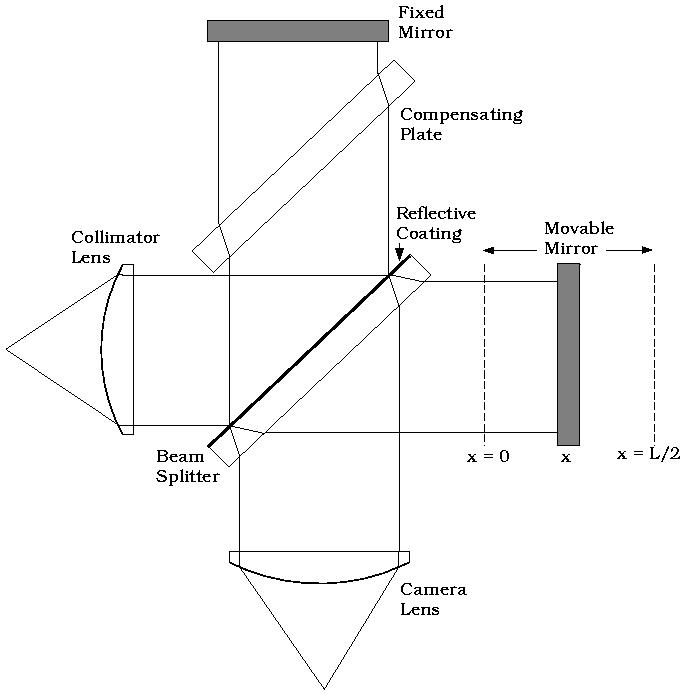
In the Fourier Transform or Michelson filter, the collimated beam is split
into two paths at the front surface of the beam-splitter. The separate
beams then
undergo different path lengths by reflections off separate mirrors before
being imaged by the camera lens at the detector. The device shown in
Fig. 2
uses only 50% of the available light. As Maillard has demonstrated at the
Canada France Hawaii Telescope, it is possible to recover this light but the
layout is more involved.
Figure 2. Schematic of a two-beam Michelson
(Fourier Transform) interferometer.
The output signal is a function of path difference between the mirrors. At
zero path difference (or arm displacement), the waves for all frequencies
interact coherently. As the movable mirror is scanned, each input wavelength
generates a series of transmission maxima. Commercially available devices
usually allow the mirror to be scanned continuously at constant speed, or to
be stepped at equal increments. At a sufficiently large arm displacement, the
beams lose their mutual coherence.
The filter is scanned from zero path length (x = y = 0) to
a maximum path length
y = L set by twice the maximum mirror spacing (x =
L / 2). The superposition of
two coherent beams with amplitude b1 and
b2 in complex notation is
b1 + b2 ei
2
where b(y) is the output signal as a function of pathlength
y and B(
The quantity b(y) - 1/2 b(0) is usually referred to as the
interferogram although this term is sometimes used for b(y). The
spectrum B(
The Michelson does not suffer the coating thickness problems of the
Fabry-Perot filter, and therefore reaches the lowest orders even
at optical wavelengths.
 is the off-axis angle of
the incoming ray and µl is the
optical gap. The condition for peaks in transmission is given in eqn. 1.
Note that
can be scanned physically in
a given order by changing
(tilt scanning), µ (pressure scanning), or l (gap
scanning).
Both tilt and pressure scanning suffer from serious drawbacks which limit
their dynamic range. With the advent of servo-controlled, capacitance
micrometry, the performance of gap scanning etalons surpasses other
techniques. These employ piezo-electric transducers that undergo dimensional
changes in an applied electric field, or develop an electric field when
strained mechanically. Queensgate Instruments, Ltd. have shown that it is
possible to maintain plate parallelism to an accuracy of
/ 200 while
continuously scanning over several adjacent orders.
is the off-axis angle of
the incoming ray and µl is the
optical gap. The condition for peaks in transmission is given in eqn. 1.
Note that
can be scanned physically in
a given order by changing
(tilt scanning), µ (pressure scanning), or l (gap
scanning).
Both tilt and pressure scanning suffer from serious drawbacks which limit
their dynamic range. With the advent of servo-controlled, capacitance
micrometry, the performance of gap scanning etalons surpasses other
techniques. These employ piezo-electric transducers that undergo dimensional
changes in an applied electric field, or develop an electric field when
strained mechanically. Queensgate Instruments, Ltd. have shown that it is
possible to maintain plate parallelism to an accuracy of
/ 200 while
continuously scanning over several adjacent orders.

 y where y is the total path difference and
is the wavenumber. If the light rays have the same intensity, the combined
intensity is 4 b2 cos2
y, where b =
b1 = b2. The combined
beams generate a series of intensity fringes at the detector. If it was
possible to scan over an infinite mirror spacing at infinitesimally small
spacings of the mirror, the superposition would be represented by an ideal
Fourier Transform pair, such that
y where y is the total path difference and
is the wavenumber. If the light rays have the same intensity, the combined
intensity is 4 b2 cos2
y, where b =
b1 = b2. The combined
beams generate a series of intensity fringes at the detector. If it was
possible to scan over an infinite mirror spacing at infinitesimally small
spacings of the mirror, the superposition would be represented by an ideal
Fourier Transform pair, such that
 )
is the spectrum we wish to determine.
B() and b(y) are both
undefined
for < 0 and y < 0: we include
the negative limits for convenience. Note that
)
is the spectrum we wish to determine.
B() and b(y) are both
undefined
for < 0 and y < 0: we include
the negative limits for convenience. Note that
 ) is normally
computed using widely available Fast Fourier
Transform methods. The construction of a Michelson filter is a major
optomechanical challenge. The ideal Fourier Transform pair is never
realized in practice. However, the Michelson filter probably comes
closest to achieving the goal of an ideal tunable filter.
) is normally
computed using widely available Fast Fourier
Transform methods. The construction of a Michelson filter is a major
optomechanical challenge. The ideal Fourier Transform pair is never
realized in practice. However, the Michelson filter probably comes
closest to achieving the goal of an ideal tunable filter.