Coevolution of Black Holes and Galaxies, 2003
ed. L. C. Ho (Pasadena: Carnegie Observatories,
http://www.ociw.edu/ociw/symposia/series/symposium1/proceedings.html)

| Carnegie Observatories Astrophysics Series, Vol. 1:
Coevolution of Black Holes and Galaxies, 2003 ed. L. C. Ho (Pasadena: Carnegie Observatories, http://www.ociw.edu/ociw/symposia/series/symposium1/proceedings.html) |
|
Abstract: We show the direction of accretion disk around the possible super massive black hole of 3C 273 or spinning supermassive black hole itself as clockwise based on the observed 3D structure of magnetic field in the jet of 3C 273. Using VLBA polarimetry, we derived distributions of Faraday Rotation Measure (RM) and projected magnetic field of 3C 273 jet. Based on a systematic gradient across the jet of RM and the projected magnetic field, the helical magnetic field is revealed, which is suggested by MHD models. The sign of RM indicates the direction of the twist of the helical magnetic field as a right hand screw. If the observed helical magnetic field is wound up by the accretion disk around possible super-massive black hole, we can see the direction of the rotation.
It is well known that jets from AGN keep narrow and well-collimated structure. In the theoretical points of view, the helical magnetic field is proposed by magnetohydrodynamic (MHD) model (e.g., Meier et al. 2001) and it is thought that helical magnetic field plays an important role of the formation and collimation of AGN jets. The helical magnetic field is wound up by the accretion disk around possible super-massive black hole or spinning black hole itself. If we find the helical magnetic field predicted by MHD models, we can investigate unobservable inside feature, such as the direction of the accretion disk or spinning black hole itself, from observable outside structure of the magnetic field in the jet.
To investigate the 3D structure of the magnetic field, a detailed analysis of both the RM and the polarization angle (PA) should be useful. For this aim, we analyzed polarimetric observations of the 3C 273 jet based on archival VLBA data.
The well-known quasar 3C 273, at a redshift of z = 0.158, is one of the brightest quasars. For a Hubble constant of H0 = 100 km s-1 Mpc-1, and a deceleration parameter of q0 = 0.5, an angular resolution of one milli-arcsecond (mas) corresponds to a linear resolution of 1.86pc. Jet components in 3C 273 display superluminal motion (Cohen et al. 1971), with apparent proper motion speeds of 4.9 to 7.7c derived from VLBI monitoring observations (Abraham et al. 1996). VLBI polarimetric observations have established that jet of 3C 273 is highly polarized (Roberts et al. 1990), which make it suitable for Rotation Measure (RM) studies.
1.2. Observations and Data Reductions
Observations were carried out on 1995 December 9 at 4.702, 4.760, 4.890, and 4.990 GHz in the 5GHz band and 1995 November 22 at 8.102, 8.240, 8.420, and 8.590 GHz in the 8GHz band using all ten stations of the VLBA. Each IF has an 8-MHz bandwidth. Both left and right circular polarizations were recorded at each station. Polarimetry images were obtained in a standard manner using AIPS and DIFMAP packages. The instrumental polarizations of the antennas were determined with unpolarized source OQ 208. Polarization angle offset at each station was calibrated by a single dish observation of OJ 287. Although the integration time towards 3C 273 was only 12 minutes at each frequency, the source is strong enough for the polarized flux densities in the jet to be detected with a sufficient signal-to-noise ratio.
We show the distribution of RM in Figure 1.1. Regions of lower fractional polarization could not give a reliable RM distribution because of the short observation time. The cross cut of the RM along line A-B is also shown in upper-right panels in Figure 1.1. There is a gradient in the distribution of RM across the C2 component.
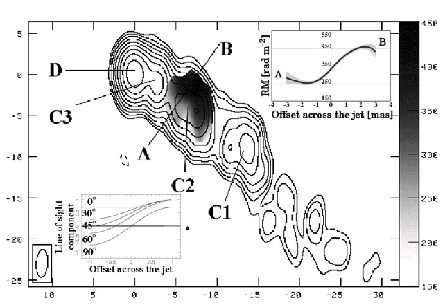 |
Figure 1.1. Distribution of RM (gray scale) superposed on the total intensity image (Asada et al. 2002). In upper-right and lower-right panels, the cross-cut of RM along the line A-B and line-of-sight component of the helical magnetic field at several viewing angle are shown (The pitch angle of the helical field is 45°.). |
The variation can be confidently associated with the jet itself, since it is unlikely that a foreground Faraday screen would produce such strong fine structure comparable to the jet width (Taylor 1998).
Faraday Rotation is produced by the invisible low energy electrons (e.g., Beckert et al. 2002). There are two possibilities for the origin of the electrons. One is due to the lower end of the non-thermal elections that have a power law distribution. The other is due to the thermal electrons that co-exist or surround the non-thermal electrons. The RM gradient is probably due to the thermal plasma surrounding the non-thermal electrons, since we could not detect a significant depolarization in component C2 between 5 and 8 GHz. If the Faraday Rotation is due to electrons which co-exist with the non-thermal electrons, depolarization should be detected. To confirm that, more detailed depolarization observation with a wide range of frequency is necessary. The low energy electrons that can be estimated by the degree of depolarization and RM would also give a clue for the composition of the jet plasma; whether it is a pair (e+-e-) plasma or normal (e-p) plasma (Wardle et al. 1998).
The systematic distribution of RM across the jet is naturally interpreted in terms of a helical magnetic field. We show the line-of-sight component of the helical magnetic field across the jet at several viewing angles in lower-left box in Figure 1.1. The toroidal component of the helical field gives gradient across the jet (see in case of 90° in Fig. 1.1.) and the longitudinal component adds an offset to the line-of-sight component (see in case of 0° in Fig. 1.1.). Apparent line-of-sight component is a superposition of these two effects. Because of the positive offset, RM in Fig. 1.1 is easily explained by the right-hand screw helical magnetic field with the small viewing angle.
1.4.3. Direction of the rotation of the accretion disk
If this helical magnetic field is due to the MHD models, we can identify that the accretion disk is rotating clockwise (as we see it), because the jet is approaching. Next to M 87 (Ford et al. 1994; Harms et al. 1994; Macchetto et al. 1998) and the maser observations of a megamaser source NGC 4258 (Miyoshi et al. 1995). we can predict the direction of rotation in the disk around possible super-massive black hole. This can be applied anything that is responsible for winding up the magnetic field like possible spinning super-massive black hole (Koide et al. 2002). It would be interesting to confirm the RM distribution in a case in which the counter jet could also be observed. The distribution should be anti-symmetric with respect to the AGN core, if the helical field is generated by the rotation of the accretion disk or the spinning black hole.
In order to investigate the inner most feature of AGN using outside feature, we have derived distributions of RM of 3C 273 jet using archival data from a VLBA polarimetry observation. The systematic gradient across the jet in the distribution of the RM is interpreted as the helical magnetic field that is suggested by MHD models. We derived the direction of the twist of the helical magnetic field as a right-hand screw from the sign of RM. It can be naturally predicted that the direction of the rotation of the accretion disk is clockwise, if the observed helical magnetic field is formed by MHD models.