

5.2. The Faint Object Camera (FOC)
The FOC (2) is one of the axial instruments on board HST. It is a photon counter that obtains images and spectra between 1100Å up to 6500Å. The FOC is diffraction limited.
The camera has two relays each with an independent optical path, filter wheels and detectors. They are named from their original (ie., pre COSTAR) focal length: f/96, f/48 and f/128. When COSTAR was installed the focal length changed to f/75.5 and f/151 for the first two. The f/128 relay due to the extremely small size is not used.
A video processor in the camera counts and determines the position of each incident photon that generated a sparkle in the photocathode. This position and number are accumulated in the memory of the instrument's computer. This activity is very sensitive to the speed with which the video processing unit reacts to the arrival of the photons. The memory unit can store 16 bits per pixel in a 512 x 512 image and 8 bits in the zoomed format of 512 x 1024 pixels.
Some characteristics of the FOC, for a 512 x 512 image, are shown in Table 6.
| F/48 | F/96 | |
| Noise | 0.002 cts/sec/pix | 0.0007 cts/sec/pix |
| Saturation limit | 0.50 cts/sec/pix | 0.65 cts/sec/pix |
| Typical FOV | 14" x 14" | 7.3" x 7.3" |
| Largest FOV | 28" x 28" | 14.6" x 14.6" |
| Scale (post-COSTAR) | 0.01435 "/pixel | 0.028 "/pixel |
| Scale (pre-COSTAR) | 0.0225 "/pixel | 0.0451 "/pixel |
The FOC has a set of 58 narrow- and broad-band filters. In particular the f/96 camera has 3 long-pass filters, 9 broad, 20 medium, 2 narrow-band in addition to the 5 neutral density filters that can be used in different combinations to perform the observations. The camera also has two objective prisms and 3 polarizers. More details about the filters can be obtained in the camera handbook.
5.2.1 Distortion
As it is essentially a cathode ray tube, the images obtained with the FOC detectors suffer from a geometric distortion. This distortion has another component due to the axial position of the camera.
To correct this distortion, reseaux marks were engraved in the
photocathode. These marks, with a 60 pixel
separation, make a 17 x 17
matrix. These "theoretical" positions are then compared to the observed
ones and the image is corrected in a such a way as to re-obtain a square
grid. This is one of the calibration steps.
5.2.2 What constitutes an FOC observation?
An FOC "observation" is composed of several files whose name starts with an X and followed by 8 alphanumeric characters. The header is a text file whose extension starts with h. The extension of the binary data starts with d.
The different files (in GEIS format) that constitute an "observation" are briefly described in the following table. More details can be found in the HST Data Handbook.
| Extension | Contents |
| Uncalibrated Data | |
| d0h /d0d | uncalibrated scientific data |
| q0h /q0d | file with data quality information |
| shh /shd | data packet describing the observation |
| ulh / uld | history of the observation |
| Calibrated Data | |
| c0h /c0d | intermediate calibration product |
| c1h/ c1d | calibrated data |
| trl | history of the pipeline calibration |
Among the FOC header keywords of interest, we can find:
| Parameter | Description |
| CRVAL1, CRVAL2 | RA and dec of the (CRPIX1, CRPIX2) pixel |
| EXPTIME | exposure time |
| ORIENTAT | position angle |
| PXFORMT | image format (512 x 512; 512zoomed x1024; etc.) |
| PHOTMODE | observing mode (FOC F/96 F486N, for example) |
| PHOTFLAM | inverse of the sensitivity |
| flux = counts x PHOTFLAM/EXPTIME | |
| PHOTZPT | magnitude zero point in the HST scale |
5.2.3 What can be found in an image?
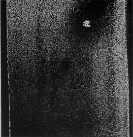
An image of the M87 jet obtained in the f/96 mode with the F430W filter and the POL0 polarizer is shown in Figure 2.

|
Figure 2. A typical FOC observation. This is an image of the jet of M87 at f/96, with the POL0 polariser. |
In this image, several common details of FOC images can be found:
5.2.4 Continuing the reduction
The reseaux can be eliminated from the calibrated image (with the c1h/c1d extensions) using, for example images.imedit or rremovex. The North direction can be determined with the compass task or with foc.focutility.north.
The approximate positions of the sources in the image can be determined using the rimcursor task.
   image = "x0i20a02t.c1h"   image to which coordinates should refer
     wcs = "world")          output world coordinate system name
wxformat = "%H")             x coordinate output format
wyformat = "%h")             y coordinate output format
  cursor = "")               image cursor
    mode = "h")
To determine better positions, this initial measurement can be complimented with images.imcntr and stsdas.toolbox.imgtools.xy2rd.
2 A detailed description can be found in
the latest edition of the intrument handbook available on-line at
http://www.stsci.edu/ftp/intrument_news/foc/html/topfoc.html
Back.