Copyright © 2013 by Annual Reviews. All rights reserved
| Annu. Rev. Astron. Astrophys. 2013. 51:63-104
Copyright © 2013 by Annual Reviews. All rights reserved |


The MC method is a general computational technique that is used widely in many different fields, including numerical mathematics, physical sciences, finance, and medicine. Its name reflects a variety of stochastic or probabilistic techniques, which all have in common that they solve equations by sampling random numbers. The MC methods are particularly interesting when applied to transport systems, which was the motivation for their first application in the 1940s. For a general overview of MC methods as a tool for transport problems, see, e.g., Dupree & Fraley (2002), Kalos & Whitlock (2009) or Whitney (2011). Its application to dust RT problems in an astrophysical context has a history of more than 40 years (see, e.g., Mattila 1970, Roark, Roark & Collins 1974, Witt & Stephens 1974, Witt 1977). In the past four decades, it has become a mainstream method for 3D dust RT calculations.
The basis of MC RT is to treat the radiation field as the flow of a large but finite number of photon packages (often called photons). Each individual photon is followed along its journey through the dusty medium. At every stage in its journey, the characteristics that determine the path of each photon (such as its birth location, initial propagation direction, or the distance along the path until the next interaction with a dust grain) are determined in a probabilistic way by generating random numbers from an appropriate probability density functions (PDF). At the end of the simulation, the radiation field is recovered from a statistical analysis of the photon paths. Hence, the MC technique simulates the RT instead of explicitly solving the RTE.
Central to all MC techniques is the process of generating random numbers from a given PDF p(x) dx. Thus an algorithm is needed that returns a set of numbers X such that the probability that X lies in the infinitesimal interval between x and x + dx is equal to p(x) dx. The starting point for such algorithms, which are key to the MC process, is a (pseudo)random number generator. This is a code that generates uniform deviates (random numbers with an equal probability to be chosen in the unit interval between 0 and 1). To generate random numbers from another, arbitrary PDF, one almost always applies appropriate operations on one or more uniform deviates. The most popular methods are the so-called transformation and rejection methods, details of which can be found in Devroye (1986) or Press et al. (2002, Ch. 7).
In the remainder of Section 5, we gradually introduce the ingredients and techniques that are combined to develop a 3D MC dust RT code. We start in Section 5.1 by describing the simplest MC RT technique, as it is the basis for all modern MC RT techniques. These simple techniques are sufficient for MC calculations in geometries with large degrees of symmetry, such as 1D spherical or slab geometries. For 3D applications, however, they would result in very inefficient codes. Fortunately, there are various weighting schemes that improve the performance of this technique, making modern MC RT quite efficient. Some of these weighting schemes have a strong heritage in RayT methods, making most modern MCRT codes hybrids between the classical MC and RayT techniques. Several of these weighting schemes were developed for 2D geometries, especially cylindrical geometries. The use of weighting schemes is critical for 3D MCRT; in Section 5.2, we discuss several of these techniques.
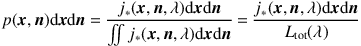
The simplest MC calculation consists of considering the RT problem at a single wavelength λ. We consider a source of photons, characterized by the source term j*(x, n, λ), and a distribution of dust, characterized by the dust density ρ(x). Throughout the calculation, the state of each photon is tabulated by its energy, position, direction of travel, and polarization state. For 3D RT, the Cartesian coordinate system is usually used, resulting in the photon's position being stored as x = (x, y, z) and the direction using direction cosines as n = (nx, ny, nz). The polarization state is stored using the Stokes vector S = (I, Q, U, V).
5.1.1. STEP 1: BIRTH. The first step in a photon's life cycle is its birth, i.e., its injection into the computational domain. If N is the number of photons in the model run and Ltot(λ) is the total luminosity of the source, the luminosity carried by each photon is L = Ltot(λ) / N . The initial position x and propagation direction n are to be chosen randomly according to the source term j*(x, n, λ), which means that they need to be sampled from the PDF
 |
(23) |
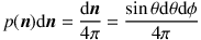
In many cases, for example, for emission by stars or thermal emission by dust grains, the emission is isotropic, which implies that the initial propagation direction can be chosen randomly from the unit sphere:
 |
(24) |
Generating random values for θ and φ from this distribution can be done easily using the transformation method. In other cases, for example, when we deal with external emission illuminating an interstellar cloud or anisotropic emission from an AGN accretion disc, different PDFs for the initial propagation direction need to be considered (see, e.g., Niccolini, Woitke & Lopez 2003, Stalevski et al. 2012). For most cases, the photon is assumed to be emitted unpolarized; i.e., S = (1,0,0,0).
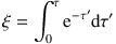
5.1.2. STEP 2: DETERMINATION OF THE INTERACTION POINT. Once the photon is launched into the dusty medium, the next step consists of randomly determining whether it will interact with a dust grain, and if so, where this interaction will take place. The PDF that describes the free path length before an interaction is most conveniently described in optical depth space, where it has an exponential distribution, p(τ) dτ = e−τ dτ. The optical depth τ to which a particular photon travels along its path before it interacts with a dust grain, is drawn from this exponential distribution. This is done easily using the transformation method: We simply pick a uniform deviate ξ and solve the equation
 |
(25) |
for τ. Integrating and solving gives τ = −lnξ (recall that the distributions of ξ and 1−ξ are equivalent). If τ is greater than the optical depth τpath to the surface of the system in the direction the photon is traveling, the photon escapes the system, and the life cycle of this particular photon is over. Otherwise, the photon will interact with the dust medium at the location along the path corresponding to the traveled optical depth τ.
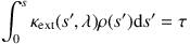
The next step is converting the traveled optical depth τ to a physical path length s, such that we can move the photon to the interaction site. This means that we have to integrate along the path and solve the integral equation
 |
(26) |
for the path length s. Comparing this equation with Equation 25 highlights the intimate link between the MC solution technique and the RayT technique: A large fraction of the calculations in MC simulations are pure RayT operations.
In practice, MC codes virtually always use a grid structure of dust cells on which the dust density and the optical properties are discretized. The integral in Equation 29 then reduces to a sum over the consecutive grid cells along the path, and the integral equation comes down to summing the optical depth along the path until τ is reached. This calculation is often one of the more computationally intensive portions of MC RT and is a strong driver for choosing a grid optimized for the particular astrophysical object of interest. For a Cartesian model grid, the distance traveled in each cell is easy to calculate, as is the next grid cell along the path. For hierarchical grids, more complex neighbor-search algorithms may be required.
5.1.3. STEP 3: ABSORPTION AND SCATTERING. Once the path length s has been calculated, the photon moves from its old location x to its updated location, i.e., the interaction site x + s n. At this location, the photon can either be absorbed or scattered; the appropriate PDF is hence not a continuous but a discrete function with only two possible values. The probability that the interaction is a scattering event is equal to the dust albedo a = κsca / κext. Using a uniform deviate ξ, the nature of the interaction is easily determined: If ξ≤ a, we have a scattering event and if ξ > a an absorption event.
In the case of an absorption event, this is the end of the photon's life cycle. If dust emission is to be calculated in the simulation, the absorbed photon luminosity is stored in the interaction cell. This absorbed luminosity will be used at a later stage to calculate the dust emission spectrum, which can then be used as the source function for another MC cycle.
If the interaction is a scattering event, the next step consists of determining the new propagation direction. In the case of isotropic scattering, this just comes down to generating a new random point from the unit sphere. In the case of anisotropic scattering, the new propagation direction n is chosen according to the PDF
 |
(27) |
where Φ(n, n', x, λ) is the scattering phase function, and n' is the original propagation direction before the scattering event. For spherical dust grains, the scattering phase function is dependent only on the scattering angle between n and n'. For the HG phase function, the most popular approximation to the real phase function, the generation of a random scattering angle and hence the calculation of the new propagation direction can be done analytically (Witt 1977). For polarized RT, the scattering process is more complex, as the scattering phase function is dependent on the polarization of the photon and, in addition, scattering changes the polarization state of the photon. A detailed description of scattering events in the case of polarized radiation can be found in, for example, Fischer, Henning & Yorke (1994); Code & Whitney (1995); or Goosmann & Gaskell (2007).
With its new propagation direction determined, the photon can continue its journey through the dusty medium. This means that the second and third steps are repeated until the photon either escapes from the system or is absorbed by a dust grain. (Cases in which the optical depth is very large and the number of scatterings is correspondingly large are possible. As a result, it is common to impose a limit on the number of scatterings to calculate. Consequently, the high optical depths are not sampled well, and there are potential systematic errors in the calculation. For most cases, the systematic errors from imposing a maximum number of scatterings are negligible.) This entire process is repeated for all the photons until the last photon has left the dusty medium. The RT at different wavelengths can be independently calculated given there is no explicit wavelength coupling in the RT. There is an implicit coupling when dust emission is included in the modeling. In this case, the absorbed luminosity at every wavelength is stored in every dust cell on the spatial grid. After finishing the simulation at all the wavelengths, the absorbed luminosity is used to compute the mean intensity J(x, λ) of the radiation field and subsequently the dust source term jd(x, λ). It is common to include the dust emission as a second source of photons by first computing the RT from the primary sources, computing the RT for the dust emission, recomputing the dust emission with the new radiation field, and iterating until a set convergence level is reached.
In simple MC RT, the output desired from the calculation is usually the view of the system from a particular observer location. Images of the system are constructed by projecting the position of each photon that escapes in the direction of the observer within some angular tolerance onto the plane of the sky. This plane is divided into pixels, and the images are built from those photons. Many of the photons will escape the system in directions other than the observer and are not counted, unless symmetries (e.g., circular or cylindrical) can be exploited. Special care must be applied when constructing the images that give the polarization state of the scattered flux, specifically the Q and U images. As part of the construction of these images, the polarization vector of the photon must be rotated so that it is referenced correctly in the image plane.
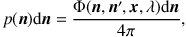
Simple MC RT is the easiest to understand, but it would be extremely inefficient for full 3D calculations. For 1D and 2D MC RT calculations, there are symmetries, such as spherical and cylindrical, that can be exploited, and thus the number of photons needed to achieve accurate results is relatively small. In the case of 3D dust RT, there are no symmetries by definition; this is one of the motivations for several acceleration methods. Most of these acceleration methods are well established and validated, whereas others still have a more experimental character. Almost all of these methods were first developed for 2D RT calculations. Figure 4 illustrates the benefits of weighted MC techniques as compared to simple MC RT methods.
 |
Figure 4. (a) Simple and (b) weighted Monte Carlo (MC) simulations are illustrated graphically. This example includes five photons resulting in one scattering photon reaching the observer and two absorption events for simple Monte Carlo radiative transfer (MC RT). This same set of five photons produces five scattered photons toward the observer and 28 absorption events for weighted MC. The improvement in computational efficiency of weighted MC is seen clearly. |
The basis of all acceleration methods is to assign a weight W to each photon and modify this weight. The weight of each photon is equivalent to the fraction of the luminosity of the emission source carried by that photon, i.e., the number of photons in each photon package. Several acceleration techniques use the idea of biasing, i.e., generating random numbers from a PDF q(x) dx rather than from the appropriate PDF p(x) dx. This biased behavior is corrected for by assigning the weight W = p(x) / q(x) to the photon. The biasing technique is used in many MC applications and can be a very effective way of reducing the variance (Dupree & Fraley 2002). It is, common practice, for example, in MC numerical integration, where it is known as importance sampling.
5.2.1. BIASED EMISSION. A direct application of the biasing technique is the so-called biased emission. The initial propagation direction of the photons launched into the dust medium is usually determined from the angular part of the source term j(x, n, λ). There are cases, however, where an increased level of emission in particular directions is desired, for example, to increase the signal-to-noise ratio in particularly interesting directions, such as the polar regions of a star with an accretion disk (Yusef-Zadeh, Morris & White 1984). In this case, the emission of photons is biased toward the directions of interest, and the initial weight of the photon is determined using the standard biasing weight formula. The same technique can also be applied to the spatial part of the source term to increase the number of photons emitted from regions with a low emission rate (Juvela 2005).
This technique of biased emission has the potential to strongly increase the efficiency of an MC simulation. However, it has the drawback that it is very model-dependent, and therefore requires significant manual interaction. It is, in a sense, comparable to the placement of the rays in the RayT method.
5.2.2. ABSORPTION-SCATTERING SPLIT. This acceleration method allows for a photon to contribute to both absorption and scattering at each interaction site. Instead of randomly choosing the nature of the interaction, the photon is split in two parts: one that is absorbed and one that scatters. The fraction absorbed is equal to (1 − a) times the current weight of the photon. For the scattered part that continues its life cycle through the dust, the weight is multiplied by a factor a.
5.2.3. FORCED SCATTERING Instead of having each photon either scatter or escape the system, the photons can be forced to scatter each time (Cashwell & Everett 1959). In the simple MC routine, the randomly generated optical depth is compared to the total optical τpath along the photon's path. This approach is problematic for regions with low optical depth: In those regions, many photons just leave the system without interacting with the dust, resulting in low efficiency of dust scattering and heating. A way to avoid this low efficiency is the technique of forced scattering, which limits the values of the randomly chosen optical depths to the range between 0 and τpath. This can be achieved by biasing the PDF from which the optical depth is generated. Instead of sampling from the actual exponential PDF, we consider an exponential distribution cut off at τ = τpath. Properly normalized, this PDF reads
 |
(28) |
Generating a random τ from this distribution is straightforward and guaranteed to produce an interaction before the photon has left the system. The compensation to be applied to the weight of the photon is a factor
 |
(29) |
One issue with forcing every scattering, when combined with the absorption-scattering split, is that there is no longer a natural stopping criterion for the scattering calculation. In the original MC cycle, photons end their journey when they are either absorbed by the dust or leave the dusty system. The common solution is to set a minimum weight for a photon, below which the photon's life cycle is terminated. The value of this termination weight is usually set to be very low, after the equivalent of many scatterings. An alternative solution is to force only the first scattering and revert to the standard scattering calculation for subsequent scatterings.
5.2.4. PEEL-OFF TECHNIQUE. For 3D cases, it is usually desired to calculate the appearance of a system for an observer at a particular orientation. Simple MC RT is particularly inefficient in building up such an image as only the photons that are emitted from the system in the direction of the observer contribute to the output appearance. In addition, some blurring of the image is inherent as photons that are within some tolerance of the desired direction are used. This inefficiency can be eliminated by requiring that all photons directly contribute to the output images by calculating the portion of the photon that is emitted from sources and scattered at every interaction point in the observer's direction (Yusef-Zadeh, Morris & White 1984). The weight factor of a photon in the direction of the observer is
 |
(30) |
where τobs is the optical depth from the position of the emission or scattering event, and p(nobs) is the probability that the photon will be directed toward the observer. For example, for isotropic emission, p(nobs) = 1, and after a scattering event we have p(nobs) = Φ(n, nobs, x, λ).
The peel-off technique is a pure application of RayT, again highlighting the connection between both approaches. Peel off is probably the most important acceleration technique for 3D MC RT simulation. It has a significant computational cost, however, as it requires a calculation of the optical depth from the emission or scattering location toward the observer after every emission or scattering event. One way to alleviate this computational burden is by precalculating the optical depth toward the observer for each cell. Another possibility is to store the information for each cell and create the images at the end of the simulation (see, e.g., Dullemond & Turolla 2000, Pinte et al. 2006, Min et al. 2009). Using a precomputed τobs or stored information to compute the image does come with a price: loss of subgrid resolution in the model images. The benefit of this approximation in decreased computation time has to be weighted against the loss of subgrid resolution for the particular modeled astrophysical object.
5.2.5. CONTINUOUS ABSORPTION. The accuracy of the re-emission of energy absorbed by the dust can be enhanced by absorbing not just at the interaction site, but also along the path the photon travels. Depending on the implementation, this can be done up to the location of the scattering event (Lucy 1999), or along the entire path (Niccolini, Woitke & Lopez 2003, Baes et al. 2011). In the latter scenario, the photon is effectively split in N + 2 different parts: one part Wesc that leaves the system (and is hence not accounted for anymore), one part Wsca that is scattered at the interaction location (determined stochastically), and N parts Wabs,j that represent the fraction absorbed in each of the N cells along the photon's path. These different fractions are, respectively,
 |
(31) |
 |
(32) |
and
 |
(33) |
where τj is the optical depth measured from the photon's location to the surface of the jth cell along the path. An alternative interpretation of this continuous absorption approach is that it estimates the mean intensity of the radiation field, not by means of the absorbed luminosity, but by means of counting the luminosity that passes through each cell. The strength of the technique lies in the fact that all photons contribute to the calculation of the absorption rate of each cell they pass through, and not only of those cells with which they interact. This is particularly useful for the optically thin regime, which has very few absorptions in the simple MC approach.
5.2.6. INSTANTANEOUS DUST EMISSION. The traditional method to computing the self-consistent dust emission in an MC RT simulation consists of running an independent MC simulation at every individual wavelength and storing the absorbed luminosity over the computational grid. In a second stage, the dust emission spectrum is calculated in each dust cell and used as a secondary source term. This approach inevitably leads to iteration, as the dust emission itself affects the radiation field. It is possible to compute the output dust emission spectrum from a multiwavelength model without iterating. The instantaneous dust emission technique or frequency distribution adjustment technique emits dust thermal photons immediately after each absorption event in a specific grid cell, with the wavelength of the emitted thermal dust photon carefully chosen to retain thermal equilibrium (Bjorkman & Wood 2001; Baes et al. 2005).
Besides eliminating the need for iteration in the computation of the dust emission spectrum, the instantaneous dust emission technique also has the advantage that photon packages are emitted at the exact position where the absorption event took place, so subgrid resolution is achieved. One disadvantage is that the absorption/re-emission event takes place in a single cell, which results in a poor convergence rate of the radiation field in cells with a low dust absorption rate. This makes the classical iterative technique with continuous absorption more efficient for 3D simulations than the instantaneous dust emission technique, at least when applied in its original form (e.g., Chakrabarti & Whitney 2009). This problem can be alleviated by applying a combination of the instantaneous dust emission and continuous absorption techniques. In this hybrid method, the photon packages are followed through the domain using the instantaneous dust emission technique, but the final dust emission spectrum of the cells, used to create images and SEDs, is calculated based on the continuous absorption approach (Pinte et al. 2006). A second problem for the instantaneous dust emission technique is that it was originally designed to work with equilibrium dust emission. Several ways have been explored to adapt the instantaneous dust emission technique for transiently heated grains (Krügel 2007, Wood et al. 2008, Heymann & Siebenmorgen 2012).
5.2.7. HIGH OPTICAL DEPTHS. In regions of high optical depth, the simple MC routine becomes very inefficient, as photons can be trapped in a virtually never-ending loop of scattering events. This problem is largely solved when the absorption-scattering split is applied, as the weight of the photon then decreases with every scattering event terminating when a very low weight is reached. However, in regions with extreme optical depths (such as in the midplane of circumstellar discs around protostars) or at wavelengths where scattering largely dominates absorption (such as the far-UV), this can still imply a significant computational burden. A solution to this problem is to mirror or reflect photons from high optical depth regions and use the diffusion approximation to find the RT solution in these regions. The diffusion approximation allows for multiple interaction steps to be calculated in a single computation. An elegant solution that is well adapted to the MC method is to solve for the RT in optically thick cells using a modified random walk technique that also uses the diffusion approximation (Min et al. 2009, Robitaille 2010).
5.2.8. POLYCHROMATISM. For multiwavelength RT, it is possible to significantly speed up the calculation by considering photon packages that consist of photons of all wavelengths. The advantage of this technique is that an MC run is simultaneously solved at all wavelengths, instead of a run for each wavelength. The difficulty in this approach is that many of the PDFs that describe the life cycle of a photon are wavelength dependent, such as the path length distribution or the scattering phase function. One solution is to consider partly polychromatic photon packages, which shift to monochromaticism as soon as wavelength-dependent PDFs are involved (Baes, Dejonghe & Davies 2005). A more advanced option is to perform the calculations at one reference wavelength λref and use the biasing technique to adjust for the wavelength-dependent PDFs (Juvela 2005; Jonsson 2006). The efficiency gains of full polychromatic RT are large given that every photon calculated can contribute to the output images and radiation field density at all wavelengths instead of a single wavelength. But there is a known significant complication – the biasing factors can be very large and, as a result, can dominate the results at a particular wavelength. This has a systematic effect on the results that is hard to control and therefore, this method should be considered experimental.
5.3. Uncertainties for Monte Carlo
In the simple (unweighted) MC RT, the noise in the output quantities (i.e., scattered intensity, polarization, etc.) scales as N − 1/2, where N is the number of photons. In the case of weighted MC, the uncertainties in the output quantities do not scale directly with N − 1/2.
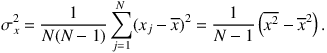
The uncertainties can be calculated by using the dispersion in the average properties of the photons used to determine an integrated quantity (Gordon et al. 2001). If the integrated quantity is X, then
 |
(34) |
where xj is the contribution of the jth photon to X, N is the total number of photons in the model run, and x is the average contribution each photon makes to X. The uncertainty in X is then σx = X (σx / x), where σx is the standard deviation of x, calculated using
 |
(35) |
The equations for the uncertainties in output quantities given above can be used to explicitly enforce a particular uncertainty level in the final results of a model run. The uncertainties in the output quantities of interest can be checked during the model run and the number of photons adjusted dynamically to achieve the desired accuracy. For example, when calculating a multiwavelength model, more photons can be added at the wavelengths with higher optical depths compared to wavelengths with lower optical depths. As the number of photons is determined from the statistics of the particular run itself, it automatically takes into account the full RT solution, including the locations of the photon sources, dust, etc. The output quantities to be used for uncertainty control can range from the global flux, to pixels in resolved images, to the radiation field density in each cell. Additionally, it is possible to improve the convergence to the needed accuracy by identifying areas of the model with high noise (e.g., particular cells with few photon interactions) and dynamically adding photons to those areas (e.g., through biased emission). Dynamically determined uncertainties to improve the convergence of a model have been used in limited cases; this is clearly an area for future improvement.
Uncertainties associated with the model setup itself are more difficult to quantify. Evaluating the systematic uncertainties due to specific model choices is usually done by trying other parametrizations or increasing the grid resolution and evaluating how the output quantities change. Example model setup choices that are prone to systematic uncertainties are the dust density grid, specific parametrizations of the photon sources, and the wavelength grid. These kinds of uncertainties are clearly the most difficult to diagnose and generally rely on the expertise of the coder and user.